
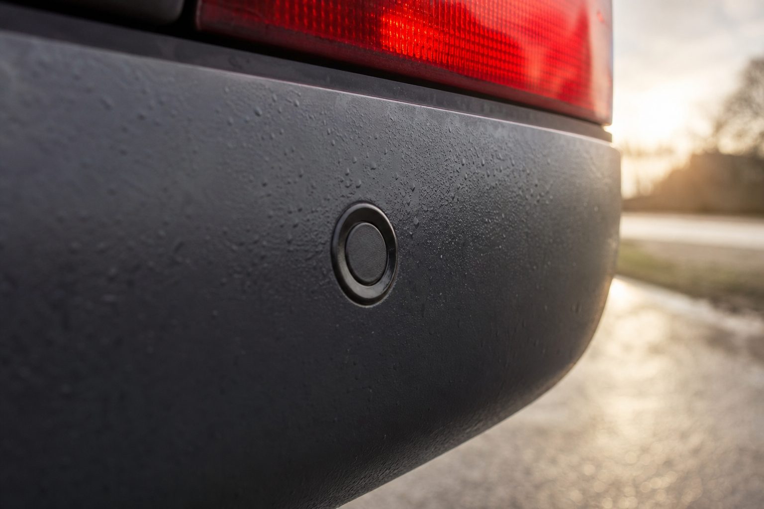
A proximity sensor that has not been calibrated correctly is worse than no sensor at all. An uncalibrated system generates false alarms — and a driver who has learned to ignore a sensor because it beeps at the vehicle’s own towbar is a driver who will not respond when the sensor detects an actual pedestrian. Calibration is not a one-time installation step. It is a recurring maintenance requirement that applies after any change to the vehicle’s configuration, after a sensor repair or replacement, and on a scheduled basis as part of fleet safety maintenance. This guide covers the parameters involved, the walk test procedure, and when recalibration should be triggered.
Proximity sensor calibration for commercial fleet vehicles involves three distinct parameters. Confusing them leads to repeated failed attempts to resolve a fault.
Most calibration problems trace back to sensor angle rather than sensitivity. A sensor that is correctly oriented and mounted will typically work within specification with its factory zone settings. Jumping straight to sensitivity adjustment before checking height and angle is the most common diagnostic error.
The baseline detection zone specification for fleet proximity sensors follows a dual-zone architecture:
FORS Silver requires proximity sensors to detect objects in the nearside zone with a functioning audible alert at all times below 20 mph. The specific zone distances are not mandated in the FORS Standard, but they must be sufficient to give the driver time to respond — which at 10 mph means a caution zone of at least 1.5 metres and preferably 2 metres or more.
Some systems allow zone thresholds to be adjusted through the controller software. Adjusting the caution zone to extend further — to 4 metres, for example — is appropriate for larger vehicles with longer stopping distances. Compressing the zones is rarely the correct calibration approach; a common mistake when a sensor generates too many alerts is to reduce the caution zone threshold rather than address the root cause (usually height or angle).
Rear proximity sensors on HGVs should be mounted at 0.8 to 1.2 metres from the ground. This height reliably detects adults and catches cyclists and workers crouching at a loading bay. Sensors below 0.6 metres are susceptible to false triggering from road debris, sloped ground, and the vehicle’s own rear structure. Sensors above 1.4 metres on a low-profile van body may miss pedestrians who are stooping or children.
For vans and LCVs making residential deliveries, the appropriate range is 0.7 to 0.9 metres — lower than for HGVs to ensure reliable detection of children at residential driveway entrances.
To verify detection height is correct after mounting:
If the sensor triggers from the ground surface at 2 metres before the board is introduced, the sensor is angled downward — not a height problem but an angle problem. Raise the sensor face to horizontal before repeating the test.
The most common angle fault is downward tilt — either from installation on a bracket that was not level, or from bracket movement caused by vibration or a minor impact. On a rear-mounted sensor, downward tilt causes the sensor to detect the vehicle’s own rear step, towbar, or the road surface immediately behind the vehicle. The symptom is a sensor that triggers immediately on engagement of reverse gear, regardless of what is behind the vehicle.
To check and correct angle:
Nearside side sensors should be parallel to the vehicle body, not angled outward or inward. An outward-angled sensor loses detection coverage close to the vehicle body — the zone that matters most at junctions. An inward-angled sensor may trigger from the vehicle’s own wheels or mudguards.
Once height and angle are confirmed, detection distance can be adjusted if the factory settings do not match the operational requirement. Fleet proximity sensor controllers adjust sensitivity in two ways depending on the system design:
Do not reduce detection distance to resolve a false alarm caused by angle or height problems. The correct fix is to address the root cause. A sensor calibrated for a 0.5-metre red zone because sensitivity was reduced to stop towbar triggering provides effectively no protection.
The walk test verifies that calibration is correct after installation or adjustment. Conduct it on level ground with the vehicle stationary, engine running (to confirm the system is drawing operational power, not standby power).
Recalibration is not a time-based interval — it is triggered by specific events. Fleet engineers sometimes raise the concern that sensors “drift” over time and need annual calibration as a matter of course. This reflects a confusion with ADAS camera calibration (which can drift). Ultrasonic proximity sensors do not drift in the same way — their sensitivity is set in hardware and does not degrade through use. Recalibration is needed when:
FORS Silver requires a functioning nearside proximity sensor. Auditors assess whether the system is operational and effective as part of the audit. While specific documentation format is not mandated, maintenance records showing walk test results and calibration checks support the audit evidence requirement. A system that generates nuisance alarms or fails a walk test will raise questions during a Silver audit.
Height, angle, and basic dip switch adjustments can be made by a competent fleet engineer who has read the installation manual. Software calibration via diagnostic port typically requires the supplier’s software tool, which may be available to trained fleet engineers or may be restricted to authorised service centres depending on the system. Walk tests can be conducted by any fleet engineer without specialist tools — they require only a level surface and a second person.
The installation manual for the sensor controller specifies the dip switch map. If you do not have the manual, contact the system supplier with the controller model number — they can provide the configuration table. Do not guess dip switch combinations; changing them without the map can produce unexpected zone configurations that are harder to diagnose than the original problem.
Almost always an angle problem — the sensor face is pointing at the vehicle’s own towbar, step, rear bumper, or ground surface. Check and correct the horizontal alignment first. If the vehicle has a genuine overhang that sits within the normal detection zone, use the overhang compensation switch or adjust the range to exclude the overhang without reducing overall coverage.
No — unless the wash dislodged a sensor from its bracket or packed mud behind the sensor face (which can affect ultrasonic signal output). After any vehicle wash, visually inspect sensor mounting and clear any debris from the sensor face. If the wash used high-pressure jets directly at the sensor, verify alignment has not shifted before returning the vehicle to service.
A seven-section checklist covering pre-calibration checks, height and angle verification, detection distance settings, rear and side sensor walk tests, and sign-off documentation — for fleet engineers calibrating proximity sensors.
Tell us what vehicles you run and what you need — we will come back with a recommendation and a price. Prefer to talk? Call 01656 721871.
Related guides: Safety Sensors for Quarry and Mining Vehicles · Reducing Blind-Spot Incidents With Sensor Systems
4 August 2026
Monday to Friday:
8.30am-5.30pm