
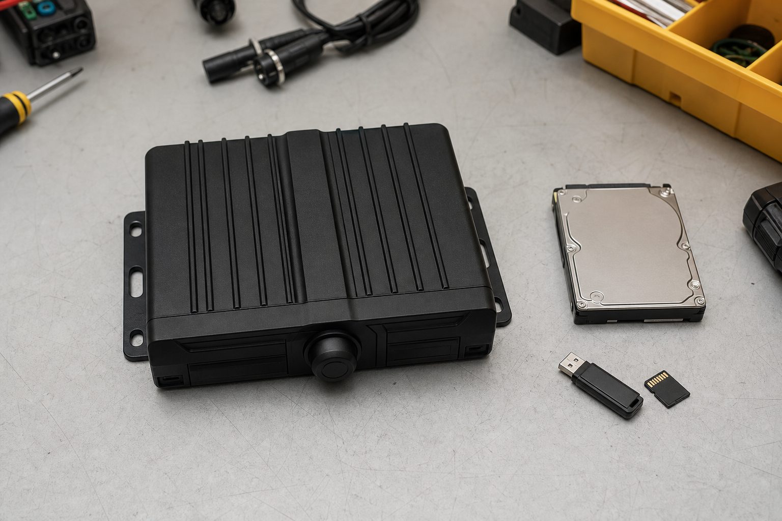
Most MDVR failures aren’t software — they’re poor power design. We’ve seen operators wake to a flat battery, fleets suffer repeated MDVR reboots at night, HDDs corrupted by brownouts, and fuses that pop the first time IR LEDs kick in. Installers routinely misidentify ACC vs constant feeds and guess cable sizes; that’s where the real downtime starts.
Scenario: you come in the morning, the car won’t start and the MDVR recorded nothing overnight. That complaint appears on forums and in fleet support calls every week — people assume “it’s the camera” when the wiring or power budget was the real problem.
This guide covers:
Who this is for: fleet managers, vehicle electricians, installers and operations teams who need reliable in-vehicle video systems that don’t kill starter batteries.
Definition:
MDVR power requirements = the device’s input voltage range, continuous and peak current draw for the recorder and attached cameras, plus wiring, fuse and battery capacity needed for reliable operation.
Quick calculation:
Wiring checklist:
Definition: MDVR power requirements: the MDVR’s accepted input voltage range, the continuous current the system draws during normal operation, the peak/inrush currents during events (HDD spin-up, IR LEDs, PoE startup), plus wiring, fuse and battery sizing necessary for safe, reliable operation.
MDVR power requirements typically cover:
12V nominal cars and vans usually operate between ~11–14.4V (engine-off vs alternator charging). 24V trucks and buses run at higher nominal voltages and may need DC-DC conversion for 12V devices. “Nominal” is not the same as “operating” — cranking and alternator spikes change real voltages, so design for real behaviour, not nameplate alone.
Power (P) = Voltage (V) × Current (I). Rearranged: I = P ÷ V. Always calculate loads in watts, then convert to amps at the system voltage used.
Continuous current is what the MDVR uses during normal recording. Peak or inrush currents occur when HDDs spin up, PoE switches power cameras, or IR LEDs turn on. These short spikes can trip fuses or cause brownouts — repeated brownouts corrupt files and shorten HDD life. Voltage drop over long cable runs worsens the problem.
MDVR 6 W + 4 cameras × 2 W = total 14 W
I = 14 W ÷ 12 V = 1.17 A continuous
Add 30% headroom -> 1.17 × 1.3 = 1.52 A -> round to 2 A fuse / 1.5 mm² cable (choose next available standard)
MDVR 8 W + HDD idle 3 W + 4 IR cameras × 3.5 W = total 8 + 3 + 14 = 25 W
I = 25 W ÷ 12 V = 2.08 A continuous
HDD spin-up peak approx +3 A -> peak ~5.08 A
Recommended fuse: continuous × 1.25 = 2.6 A -> choose 3 A slow-blow or 5 A for inrush; cable 2.5 mm²Voltage drop reduces the voltage at the MDVR; if a device needs 11 V minimum, a drop can push it below that threshold and cause reboots. Aim for <3% drop (≈0.36 V on 12 V). For long runs, increase conductor size, use a local DC-DC converter near the device, or power a PoE switch locally.
Include the MDVR’s PoE budget when summing watts (example: 60 W total available across ports). IR and heaters create variable peak draws — if the MDVR’s PoE budget is insufficient, use an external PoE switch with its own power supply.
| Solution | Typical use-case | Upfront cost | Reliability vs battery drain | Installation complexity | Best for | Short downside |
|---|---|---|---|---|---|---|
| Direct vehicle battery (constant/B+) | Always-on recording, telematics | Low | High drain risk if unmanaged | Low | Fleets needing 24/7 power (if battery isolated) | High risk of flat battery without cutoff |
| ACC-switched (ignition) | Normal driving recording; avoids overnight drain | Low | Protects starter battery; not for parking | Low | Taxis, drivers who don’t need parking mode | Misses overnight/park events |
| Relay-to-auxiliary battery | Separate battery for parking mode | Medium | Reliable; isolates starter battery | Medium | Long-haul fleets, taxis needing parking mode | Requires battery management/charging |
| DC-DC isolated converter/regulator | Vehicles with 24V or sensitive electronics | High | Stable voltage; protects devices | Medium–High | Trucks, buses; multi-voltage fleets | Cost and complexity |
| External PoE switch / power pack | Many PoE cameras, long deployments | Medium–High | Removes PoE load from MDVR | Medium | Vans, buses with many cameras | Extra box to fit; additional wiring |
Decision rules:
Limitations: clamp meters often smooth short spikes — use peak-capable meters or loggers. Inline ammeters require breaking the positive cable — do this safely and fuse the setup.
Decision criteria: unattended runtime (hrs), camera count & IR usage, vehicle voltage (12V/24V), existing dual-battery, ambient temperature, regulatory uptime needs.
| Use-case | Recommended solution |
|---|---|
| Short local trips (1–4 hrs) | ACC-switched; no parking mode needed |
| Taxis/private hire (10–14 hr shifts) | ACC-switched for driving; auxiliary battery or DC-DC for parking surveillance |
| Long-haul trucks (24V, many cameras) | DC-DC converter + auxiliary battery; wide-input MDVR or 24V MDVR |
| Coaches/buses (many PoE cameras) | External PoE switch with own PSU or DC-DC + PoE switch |
| Plant machinery (infrequent charging) | Dedicated battery pack with low-voltage disconnect; consider solar trickle |
Operators running 12–14 hour shifts will need an auxiliary battery or they’ll get flat batteries every other week — we’ve seen it repeatedly.
Safety call-out:
Always isolate the battery before work. Place the primary fuse within 300 mm of battery positive. Use appropriately rated lugs (M6/M8) and torque to manufacturer spec. If unsure, get a qualified vehicle electrician.
Rule-of-thumb callouts:
| Continuous current (A) | Recommended minimum conductor (mm²) | AWG equivalent | Max one-way length for <3% drop at 12V | Notes |
|---|---|---|---|---|
| 0–5 A | 1.0 mm² | AWG 18 | up to 6 m | suitable for MDVR-only short runs |
| 5–10 A | 1.5 mm² | AWG 16 | up to 6–8 m | typical small MDVR + 2 cameras |
| 10–20 A | 2.5 mm² | AWG 14 | up to 6–10 m | MDVR + multiple cameras/HDD |
| 20–35 A | 4.0 mm² | AWG 11 | up to 10–15 m | PoE switch or multiple loads |
| 35–60 A | 6.0 mm² | AWG 9/8 | up to 15–20 m | heavy inrush systems or multiple devices |
Note: these are conservative starting points. Convert AWG to mm² for UK installs and check local regs. If in doubt, upsize conductor.
| Symptom | Likely cause | Quick tests | Immediate fix | Long-term fix |
|---|---|---|---|---|
| Reboots at night | Peak IR draw / brownout | Measure night voltage & current | Temporarily disable IR or reduce camera brightness | Increase headroom, upgrade cable/fuse, add auxiliary battery |
| Flat battery after overnight | Continuous draw on constant feed | Measure overnight current draw | Disconnect constant feed or switch to ACC | Fit low-voltage cutoff, auxiliary battery or DC-DC isolator |
| HDD corruption after power loss | Abrupt shutdown / brownout | Check logs and file system | Avoid further writes; use SSD for critical data | Add UPS/buffer or move to SSD |
| Fuse keeps blowing at startup | Inrush too high or wrong fuse type | Measure startup current | Replace with slow-blow or use relay | Correct fuse sizing, add inrush mitigation |
| Cable warm/hot | Undersized cable or poor termination | Visual & thermal check | Reduce load or shutdown | Replace with correct gauge, re-crimp and protect |
Calculate the loads, allow sensible headroom, protect cables and fuses, and test under real conditions (including night and cranking). For parking surveillance, the extra cost of an auxiliary battery or DC-DC solution is often cheaper than the downtime and repairs caused by flat starter batteries or corrupted footage.
If a small extra installation cost avoids repeated callouts and lost evidence, it’s worth it.
What voltage does an MDVR need?
Most MDVRs accept 12–24V nominal input (many wide-range units accept ~8–36V). Check the device spec sheet. For 12V vehicles expect 11–14.4V operating range; 24V vehicles operate at higher nominal voltages.
How do I calculate MDVR current draw?
Sum continuous watts of MDVR + peripherals, then divide by vehicle voltage (I = W / V). Add 20–30% headroom and account for device inrush.
What wire size should I use for an MDVR?
See the wiring chart in this guide. As a rule: under 5 A use ≥1.0 mm²; 10–20 A use ≥2.5 mm²; above 20 A use 4.0 mm² or larger depending on length.
Do I need a fuse and where to place it?
Always fuse at the battery positive within 300 mm of the battery. Fuse rating = continuous current × 1.25 (choose nearest standard fuse) unless manufacturer specifies otherwise.
Which is better: SSD or HDD for MDVRs?
SSDs use less power and tolerate abrupt power loss better; HDDs offer larger capacity but draw higher peaks and are vulnerable to repeated brownouts.
How can I prevent a flat battery from MDVR?
Use ACC-switched power for normal operation, add a low-voltage cutoff, or fit an auxiliary battery / DC-DC isolator for parking surveillance.
Should PoE cameras be powered from the MDVR?
Only if the MDVR’s PoE budget covers peak camera draw. For many-camera systems consider an external PoE switch with its own supply.
How do I test peak/inrush current?
Use a meter that captures peak current or a data logger. Bench-test with an adjustable power supply and simulate camera IR and HDD spin-up.
Download our free 8-phase checklist to plan, wire, commission and sign off every MDVR power installation — includes a cable sizing chart, current calculation worksheet and sign-off form.
Related guides: How an MDVR Integrates With Your Vehicle Camera System · What Is an MDVR and How Does It Work?
Tell us what vehicles you run and what you need — we will come back with a recommendation and a price. Prefer to talk? Call 01656 721871.
4 August 2026
Monday to Friday:
8.30am-5.30pm