
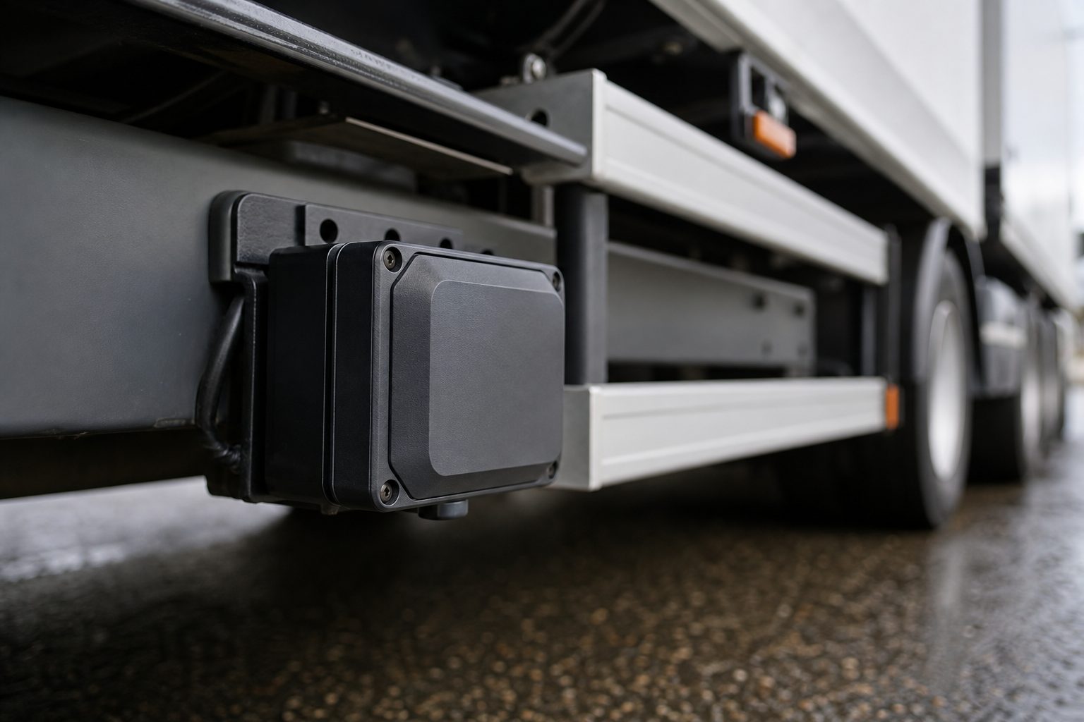
A proximity sensor and a camera cover the same blind spot. One tells the driver an object is close; the other shows what it is. Fitted separately and wired to separate displays, they divide the driver’s attention at exactly the moment it should be focused. Fitted as an integrated system, they work as a single alert: the sensor triggers, the camera feed opens on the display, and the driver sees and hears the hazard simultaneously. The difference between the two approaches is not hardware — it is wiring and configuration.
In a basic installation, proximity sensors and cameras run independently. The sensor controller has its own output — usually a buzzer or a standalone display with a zone indicator. The cameras feed to a separate cab monitor. The driver must watch both outputs and mentally combine them to understand what is happening around the vehicle.
Integration means routing both signal types through a common controller or MDVR (Mobile Digital Video Recorder) so that they respond to each other. At its simplest, this means the sensor alarm triggers the camera display to switch automatically to the relevant view. At its most complete, it means sensor zone data is overlaid directly onto the camera image, with distance indicators displayed on screen alongside the visual feed.
Three integration modes are common in fleet installations:
In most commercial fleet installations, the MDVR is the component that makes integration possible. It receives video inputs from all cameras — rear, nearside, front, internal — and can also accept trigger inputs from the sensor controller. When the sensor signals a detection event, the MDVR routes the appropriate camera feed to the cab display and flags the event for recording.
Multi-channel MDVRs used in fleet applications typically handle four to eight camera inputs simultaneously. Integration with proximity sensors adds an additional input layer — not a video feed, but a digital trigger signal that tells the MDVR which camera to prioritise and whether to mark the clip as an event recording. This means that every time the sensor detects an object in the red (stop) zone, the corresponding camera footage is automatically timestamped and flagged — creating an evidence record without any action from the driver.
This matters for FORS-audited fleets and for incident management. When a collision or near-miss occurs, the operator needs footage from the moment of the sensor alert, not from thirty seconds before. An integrated system records the right clip automatically. A non-integrated system requires an engineer to search manually through continuous footage to find the moment that corresponds to the sensor event.
A question that fleet safety managers raise consistently when specifying systems: if I have cameras with good coverage, do I still need proximity sensors? The answer is yes — because the two technologies have fundamentally different strengths.
Cameras provide context. They show the driver what is in the detection zone — a pedestrian, a bollard, a kerb, another vehicle. A good reversing camera with a wide-angle lens gives the driver a picture of the space behind the truck that mirrors simply cannot replicate.
Sensors provide measurement. Ultrasonic proximity sensors detect the distance to the nearest object in their detection zone and return a warning in under 0.2 seconds. They work in conditions where cameras struggle — at night without infrared, in direct sun glare, or when a camera lens is obscured by rain or spray. They trigger an alarm even when the driver is not looking at the camera display.
The risk with cameras alone is that the driver must actively watch the screen. The risk with sensors alone is that the driver knows something is there but cannot see what it is or where exactly it sits. Integration removes both gaps: the sensor ensures the alert happens even if the driver is not watching the display, and the camera ensures the driver can see what the sensor has detected.
The practical trigger sequence in a well-integrated system works like this:
The key element in this sequence is that the display switch at step 2 happens automatically — the driver does not need to manually select the reversing camera view. On vehicles where the driver is looking at a route plan or managing a delivery manifest, the sensor-triggered display switch is what catches their attention before the alarm escalates.
For vehicles with 360° camera systems — four or more cameras providing a complete bird’s-eye view of the vehicle — integration with proximity sensors works by zone mapping. Each sensor zone corresponds to a camera feed. When the nearside rear sensor triggers, the 360° display automatically highlights the nearside rear quadrant of the surround view. When the front corner sensor triggers, the front camera feed comes up.
This configuration is most useful on vehicles that operate in tight yards, loading bays, or multi-directional site traffic — where the driver may need to reverse, swing wide, and then pull forward in a single manoeuvre. The integrated 360° system tracks objects in all zones simultaneously and presents the driver with the most relevant camera angle at each moment without requiring manual selection.
The sensor layer adds a dimension that cameras alone cannot provide in this configuration: the distance measurement. A 360° camera view tells the driver there is a pedestrian to the nearside. The sensor tells the driver they are 1.2 metres away and closing. Both pieces of information are needed to make the correct decision.
The most complete integration extends beyond the cab to fleet management software. MDVRs that connect to a telematics platform can transmit sensor event data alongside the camera footage clip — allowing fleet managers to review not just the video of an incident, but the sensor data that triggered it, including which zone, at what distance, and at what point in the journey.
This has two practical uses. First, incident management: when a driver reports a near-miss or an insurance claim arrives, the telematics platform provides a corroborated record — the sensor detected an object at 0.8 metres at this GPS coordinate at this time, and here is the camera footage from that moment. Second, behaviour review: if a sensor is triggering frequently on a particular route or at a particular depot, the combined sensor + GPS data shows exactly where the problem is occurring and whether it reflects a genuine hazard or a calibration issue.
The most common integration error is treating sensor installation and camera installation as separate projects with separate budgets and separate installers. Systems specified this way are rarely integrated at the controller level — each system has its own display, its own alert logic, and the driver must manage two separate safety interfaces. Drivers who have experienced this describe it exactly as you would expect: two things beeping at different times, neither of which tells them what the other one is doing.
The correct approach is to specify sensor and camera integration as a single system from the outset, with a shared MDVR capable of handling both trigger inputs and camera channels, and a single cab display that shows both outputs through a unified interface. The hardware cost difference is small — the MDVR required for integration is the same MDVR needed for multi-camera recording. The configuration cost is recovered immediately in reduced driver training requirements and improved uptake.
Not always. In many cases, existing cameras can be re-routed through an MDVR that supports trigger inputs, and the existing sensor controller output can be wired to the MDVR as a digital trigger. An engineer assessment of the current wiring is needed to determine compatibility before assuming a full replacement is required.
Yes — MDVR systems with zone-mapped trigger inputs can be configured to route specific sensor zones to specific camera channels. Rear sensor → reversing camera, nearside sensor → nearside camera, front sensor → front camera. This mapping is set up during installation.
On integrated systems, the MDVR flags the clip from the triggered sensor event as a flagged event recording. These are preserved separately from continuous loop recordings, which are overwritten as storage fills. Event recordings are retained until manually deleted or exported.
No. Sensor data is a trigger input to the MDVR — it does not affect the video signal from the cameras. Image quality is determined by the camera specification and the MDVR’s encoding settings.
FORS Silver requires a functioning nearside proximity sensor with audible alert and a nearside camera. The standard does not mandate integration between the two, but an integrated system is the more practical implementation — and auditors view integrated systems more favourably when assessing the effectiveness of the safe system as a whole.
A 5-section installation checklist covering MDVR setup, camera wiring, sensor trigger integration, cab display verification, and final walk test — for fleet engineers and FORS audits.
Tell us what vehicles you run and what you need — we will come back with a recommendation and a price. Prefer to talk? Call 01656 721871.
Related guides: Common Sensor Faults and How to Fix Them · UK Regulations for Safety Sensors
4 August 2026
Monday to Friday:
8.30am-5.30pm