
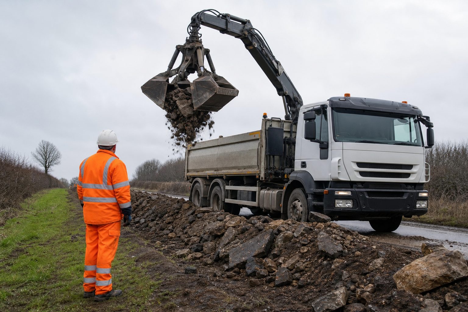
Tippers fitted with generic HGV camera configurations consistently produce two specific failure modes. The rear camera — mounted on the tipping body — is pointing at the sky the moment the body is raised, exactly when the vehicle needs rear coverage during the reverse that follows a tip delivery. The g-sensor — calibrated for road events — fires an alert on every tipping cycle, generating a false event log that drivers and fleet managers learn to ignore. Both failures are solved by a camera specification that accounts for how a tipper actually operates, not how a standard delivery HGV works.
FORS Silver v7 and CLOCS v5 define the minimum camera and sensor requirement for road-going construction vehicles. For a rigid tipper over 7.5 tonnes — which covers most construction aggregate tippers — the minimum is: nearside camera with in-cab display, rear camera, left-turn audible warning with night mute, nearside proximity sensor, and reversing alarm (MOIS front detection is not mandatory but is recommended).
This is the entry point. It is the spec that gets a tipper through the site gate at a CLOCS-adopting site and satisfies a FORS Silver audit. But the standard baseline, applied without modification to a tipper body, produces a system that technically passes audit and practically fails the operating environment. The camera positions and calibration thresholds designed for a box van or curtainsider do not transfer directly to a tipper.
The most consequential mounting decision on a tipper is where the rear-facing camera is fixed. On a standard delivery HGV, the rear camera mounts on the rear face of the body — there is no moving part. On a tipper, the rear body raises to a significant angle during the tip cycle. A rear camera mounted on the tipping body rises with it. The in-cab display shows the sky, the ground at an angle, or the inside of the body aperture — not the reversing zone behind the vehicle.
The reverse that follows a tip delivery is a high-risk manoeuvre. The vehicle is on a site, often in a confined area with banksmen, plant, and site workers nearby. The driver needs rear coverage at this exact moment. A body-mounted camera provides no useful coverage during this manoeuvre.
The solution is chassis mounting — positioning the rear camera on the chassis frame or a fixed structural bracket below the tipping body. The camera is fixed relative to the vehicle regardless of body position. It maintains a level, consistent view of the rear of the vehicle and the reversing zone whether the body is fully lowered, mid-raise, or at full tip angle.
Chassis-mounted rear cameras on tippers require a protective guard bracket. The mounting position is exposed to aggregate spillage from the tailgate, stone wash-back during tip, and material passing through the body when the tailgate opens. A camera without a guard bracket accumulates stone impact damage that degrades both the housing and the lens within a short operational period.
A tipper grab — also called a grab lorry — adds a hydraulic crane arm and grab jaw to the tipping body. The arm extends from a rotating base mounted behind the cab and is used to load and unload bulk material, collect from demolition rubble piles, or place material in locations the tipper body cannot reach directly. The grab arm creates a hazard category that does not exist on a standard tipper.
During grab operation, the arm extends laterally and overhead — the sweep zone covers a wide radius around the vehicle. A question that comes up consistently when tipper grab operators review their incident records is why standard camera kits fail to capture near-misses during loading: the answer is that no camera in the standard five-position configuration is positioned to show the arm’s working zone.
The most effective camera position for grab arm coverage is mounted on the grab arm mechanism itself, angled to show the claw zone and the area directly below the arm during deployment. This camera travels with the arm, maintaining a view of the active working zone throughout the loading cycle. On MDVRs, this feeds the in-cab display as a dedicated channel activated when the grab function is engaged.
A secondary wide-angle camera at cab roof level covers the overhead sweep arc during slew — the zone before the arm reaches its deployment position. Together, the arm-mounted camera and the cab-roof wide-angle cover the full grab operation zone that poses the most significant site incident risk for tipper grab operators.
Tippers with a significant gap between the cab and the leading edge of the tipping body create a nearside blind zone that standard wing-mirror camera positions may not cover. A camera mounted on the mirror wing post or the cab side covers the zone alongside the cab. The gap between the cab and the body — particularly on tippers with a chassis extension or sub-frame — may be visible to neither the mirror nor a cab-mounted nearside camera.
A second nearside camera at the leading edge of the tipping body closes this gap. For tippers working in confined site environments with pedestrian traffic alongside the vehicle, this coverage gap is a genuine hazard point. Site workers crossing between the cab and the body on the nearside during loading or positioning are in a zone that a single nearside camera does not resolve.
Road-calibrated g-sensors on tippers generate false events on every tipping cycle. The hydraulic raise of the tipping body creates a longitudinal articulation and vibration event that is, to a road-calibrated system, indistinguishable from a harsh braking or impact event. On a vehicle that tips multiple times per shift, this produces a continuous false event log that obscures genuine road events in the data stream — and that drivers and fleet managers quickly learn to dismiss entirely.
Calibration for tipping operations requires either a sensor ECU that can exclude defined movement signatures, or sensitivity adjustment that raises the trigger threshold above the tipping cycle range. The appropriate method depends on the MDVR and sensor ECU specification — not all systems support tipping cycle exclusion natively. Confirm this capability before specifying the MDVR for a tipper fleet.
Proximity sensors face the same calibration requirement. Standard detection ranges of 2.5–3 metres generate continuous alerts in confined site environments where the vehicle operates close to plant, site boundaries, and banksmen throughout the working day. Site proximity detection ranges for tippers are typically adjusted to 1.5–2 metres for active alert zones.
Tippers in aggregate, quarry, and demolition environments expose cameras to stone strike as a routine condition. A tipper loading from a crusher, reversing under a hopper, or tipping at a demolition site operates in a stone-strike environment on every cycle. Camera housings rated to IP67 but built to semi-professional specifications fail under repeated stone impact within weeks of installation on a working tipper.
The appropriate specification for tipper cameras is IP67 minimum throughout, IP69K for the rear camera and any camera in the direct path of material flow during tipping. Impact-resistant industrial-grade housings — not consumer-grade or semi-professional units — are necessary for chassis positions that receive direct stone strikes. Cable runs in full conduit throughout, with no unprotected sections: stone strike on unprotected cable runs damages cabling progressively, producing intermittent faults that are difficult to diagnose and expensive to repair on-vehicle.
Yes. The rear camera must be mounted on the chassis or a fixed structural point — not on the tipping body. A body-mounted rear camera loses its rear view the moment the body is raised, exactly when rear coverage is needed during the reverse following a tip. Chassis mounting keeps the camera level and functional at all body positions.
A tipper grab requires grab arm zone coverage — a camera mounted on the grab arm mechanism showing the claw zone and the area below during deployment, plus a wide-angle camera at cab roof level covering the overhead sweep arc. Neither of these positions is included in a standard five-camera configuration.
Yes, consistently, if the g-sensor is calibrated for road use. The hydraulic raise of the tipping body generates vibration and articulation that road-calibrated sensors register as events. Calibration to exclude the tipping cycle — through ECU signature exclusion or raised sensitivity thresholds — is required for tippers with active event monitoring.
IP67 minimum for all external cameras; IP69K for the chassis-mounted rear camera and any camera in the path of material flow during tipping. Impact-resistant industrial-grade housings are required — stone strike is a routine operating condition on aggregate and demolition tippers, and semi-professional housings degrade under repeated impact.
Yes. A rigid tipper over 7.5 tonnes requires the full FORS Silver v7 equipment standard for CLOCS site access: nearside camera with in-cab display, chassis-mounted rear camera, left-turn audible warning, nearside proximity sensor, and reversing alarm. Non-compliance results in site gate refusal at CLOCS-adopting sites.
A printable checklist covering chassis rear mounting, grab arm zone cameras, nearside gap coverage, g-sensor and proximity calibration, IP ratings, and FORS Silver v7 / CLOCS v5 compliance for tippers and tipper grabs.
Tell us what vehicles you run and what you need — we will come back with a recommendation and a price. Prefer to talk? Call 01656 721871.
Related guides: Camera Requirements for Construction Fleets · Live View for Construction Sites
4 August 2026
Monday to Friday:
8.30am-5.30pm